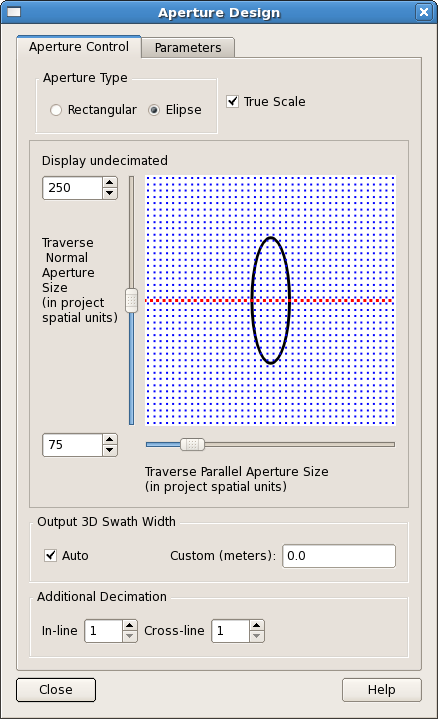
Click the "Aperture Design”  icon or select “Tools->Aperture Design...” from the main menu. This dialog comprises two tab panes, the Aperture Control tab and the Parameters tab.
A feature in this release is the interactive schematic diagram to assist the User in SFE processing aperture geometry design. By moving the sliders to adjust the normal and parallel axes dimensions the User can see how many input points will be stacked to create an output point. The User can select either “Rectangle” or “Ellipse” as the aperture type, together with information to specify the aperture inline and xline dimensions. It is recommended the Output CMP Interval be set to the same as the input trace interval. The default is 12.5.
As a rule of thumb an expert user of the SFE software suggestion for aperture dimensions as in the following quote:
“I tend to use a crude 5 x 2 ratio of line normal to line parallel. Typical for a confined channel system 1-2 km across, with traverse picked down axis I would use 1000m x 200m (i.e. 500m either side of the traverse, and 100m either side of a point along the traverse length). You may have to vary depending on the geology and also data quality. The disadvantage of going too far from the median traverse is not being exactly sure where the stacked events are coming from.”
For more information see section Aperture Geometry and Appendix A - Aperture Geometry.
There are two control items on this tab pane; Maximum Aperture and Navigation Parameters.
The Maximum Aperture control is used to increase or decrease the maximum axis value available to the Aperture Control sliders. Currently this is defaulted to 500 “project units”. If this value is not appropriate then modify the value here by either typing a new maximum value or by clicking the up or down arrows on the Spin Box. On switching back to the Aperture Control tab it will be seen that the scale of the diagram has changed to reflect the new maximum aperture value.
