This appendix attempts to explain the aperture geometry. Various users have been confused as to what is meant by the inline and xline aperture sizes.
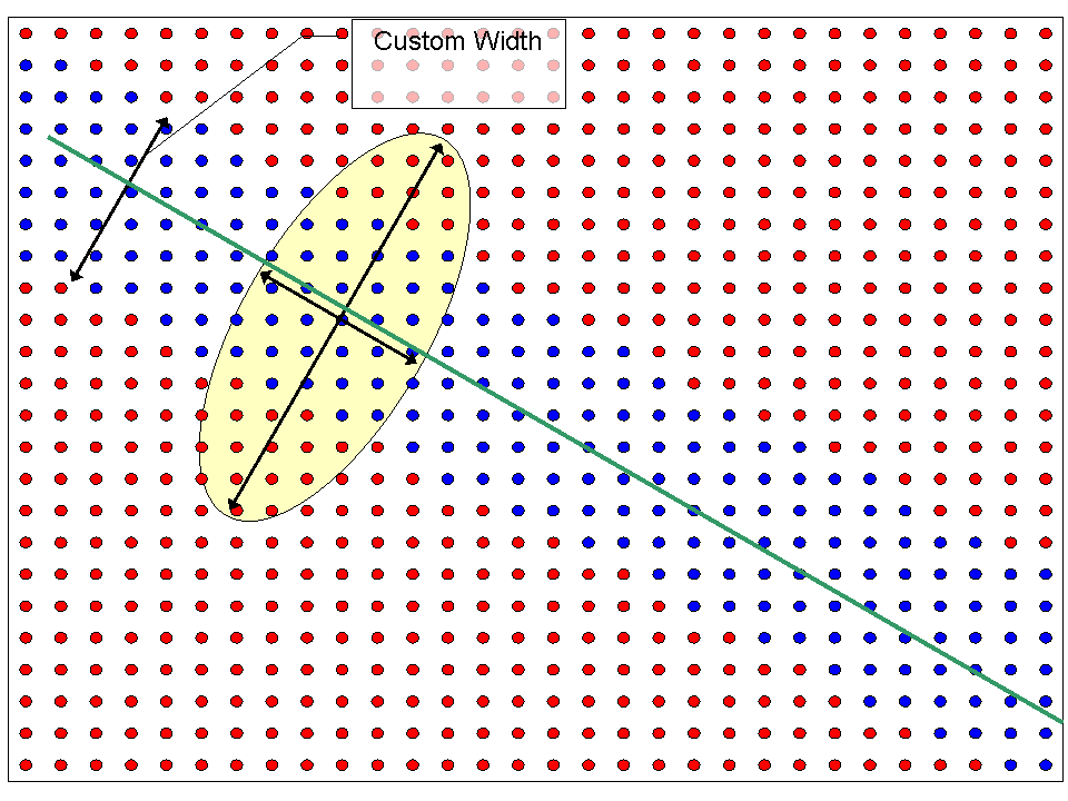
The diagram below shows the position of a number of traces (red dots) in a 3D seismic survey. A 3D SFE traverse (green line) segment is positioned over this 3D survey defined by a pair of inline/xline knee points. Within the traverse output, trace locations (blue dots) have been positioned on those input 3D traces which are closest to the traverse (Auto swath width mode). An aperture (ellipse coloured pale yellow) is laid over the 3D traces centred on one of the output 3D traces. The area of the aperture is defined by two parameters, namely the inline trace aperture size and the xline aperture size. The inline aperture size is the distance between one edge of the ellipse and the opposite edge of the ellipse in the direction (parallel) of the 3D SFE traverse segment. The xline aperture size is the distance between one edge of the ellipse and the opposite edge of the ellipse in the direction that is perpendicular (normal) to the 3D SFE traverse segment.
Figure A.1. Aperture Geometry for 3D SFE Traverse with Auto swath width off and Custom Width set to some value other than zero

If the user wishes to generate parallel 3D SFE traverses, then this can easily be achieved by turning off the “Auto” checkbox item and setting the Custom Width field(in project's spatial units) to some value other than zero. The diagram above shows the effect of setting the swath width. Here the traces (coloured blue) show a swath of SFE traces being generated.