To open the Aperture Control dialog click on the “Aperture Design” icon or select “Aperture Design…” from under the “Tools” menu pull-down.
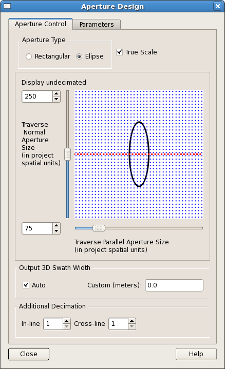
This dialog allows the user to design the aperture geometry around each output 3D traverse trace. The schematic diagram shows the effect of changing the various design controls. Input points are represented by blue dots and output points (the traverse) is represented by red dots. The schematic instantly shows the size and orientation of the aperture in relation to the input grid and shows how many input points will contribute to an output location.
Two types of aperture are supported: "Rectangular" and "Elliptical". In both cases the aperture is orientated according to the direction of the current traverse segment (see Appendix A - Aperture Geometry).
The "Traverse Parallel Aperture Size" is the aperture size in the direction (parallel) of the current traverse segment, and the "Traverse Normal Aperture Size" is the aperture size perpendicular (normal) to the traverse segment. Slider bars are provided to adjust the aperture dimensions. Clicking either side of the slider will increment its value in multiples of 10. Input fields have also been provided to input the aperture sizes. These allow exact aperture sizes within the range set by the “Aperture Max” (set on the “Parameters” tab). The absolute maximum value permitted is 5000 “projects spatial units”. As the “Aperture Max” value is increased so the number of points (both input and output) on the diagram is decimated. This decimation is for visual purposes only and is provided to ensure the density of points does not become so great that the diagram ceases to be useful. Above an Aperture Max of 500 the display is decimated by 2, above 1000, by 3, and so on. The amount of decimation is shown on the dialog. The aperture input fields and aperture sliders are synchronised.
When the “True Scale” check box is “checked” then the diagram shows the aperture in relation to a fixed grid size (i.e. moving the sliders increases or decreases the size of the aperture). When the box is “un-checked” then the aperture occupies the full size of the diagram and the scale of the input and output points are adjusted accordingly. Moving the sliders changes the scale of the diagram such that one of the aperture’s axes always occupies the full size of the diagram.
Additional decimation of input in-lines and cross-lines are provided using the "In-line" and "Cross-line" spin-boxes. These "In-line" and "Cross-line" decimation items are used to allow larger apertures to be specified without running out of virtual memory. SFE requires all input traces within the aperture to be loaded to memory before processing can begin. By using the additional decimation parameters the User can skip between 2-10 input in-line and input cross-line traces within the aperture, thus reducing the total virtual memory requirements.
The “Output 3D Swath Width” allows the user to control the width of the output SFE 3D traverse. By default, the SFE processing will generate sufficient SFE 3D traces along the traverse that if the user were to display this traverse in a viewer, there wouldn’t be any dead (undefined) traces. However, if a parallel traverse were selected for display by the user, then dead (undefined) traces would start to appear on such displays. This might occur even if the user were to shift the traverse by a relatively small amount. In 3D mode the user has the option to do processing on parallel traverses. This is achieved by turning off “Auto” and setting the “Custom Width” of the SFE swath. Note: increasing the swath width in this way can dramatically increase the run time of SFE.
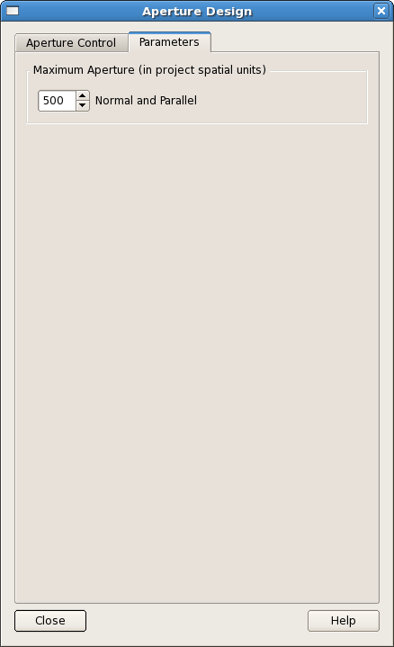
The only item on the Parameters tab is the “Aperture Max” spin box. This allows the User to change the maximum Aperture value which is used to control the scale of Aperture design diagram. The values increase or decrease by 100 as the User clicks the up or down arrows. Alternatively you may enter any value up to an absolute maximum of 5000 (project spatial units).