This section describes the paramter testing facility within SsbQt.The Parameters test panel can be accessed by pressing the  button on the tools menu bar.
Using this panel, it is easy to test how much a change of one or more parameters can affect the calculated operator. A range of candidate values for one or more parameters can be entered, and the effects of these changes can be conveniently viewed.
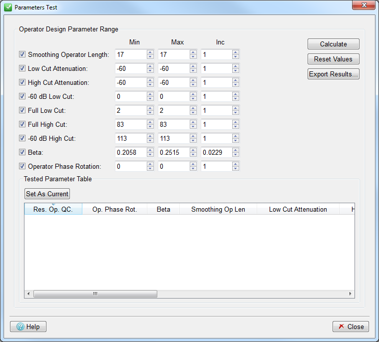
The parameters that can be adjusted come from the Design Controls Dialog and they consist of:
Smoothing Operator Length value.
Low and High Cut Attenuation values.
Design Operator -60dB Low and High Cut values.
Design Operator Full Low and High Cut values.
Fit Well Log Curves Beta value.
Seismic Operator Phase Rotation Angle.
For each of the parameters mentioned above you can set a minimum, maximum and increment value. You can also include or discard a certain parameter from the test by using the checkbox next to it.
To run the parameter test you must click the Calculate button, and the Residual Operator QC Correlation Coefficient value will be calculated for each combination between different values of all the parameters that are ticked. In the following example Full Low Cut has been requested between the values of 0 and 3 Hz and the Full High Cut between 74 and 85 Hz.
Note that if ASCII logs without position information have been used then it is not possible to use these to calculate an Average Correlation value, so the Correlation column will be filled with zeros.
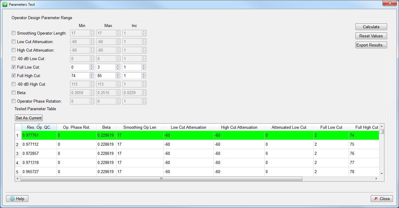
The results for the parameter test are then shown on the table. The row in light green corresponds to the parameters combination that gives the best Residual Operator QC Correlation Coefficient value.
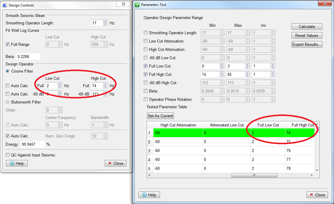
To see the immediate effect of a set of parameters both in the Seismic View, and in the Design Controls panel, click on the row to select it, and then use the Set As Current button (or double-click on the row). The diagram below shows that row 1, with Full Low cut of 2 Hz and Full High Cut of 74 Hz has been selected. The values 2 Hz and 74 Hz can be seen in the Full Low and High Cut fields in the Design Controls panel.
The effect of a row of values can also be seen by double-clicking in that row.
If you want to export the results to a file you can use the Export Results button, which will prompt you for a text file to write them to.
Finally, the button Reset Values can be used to reset each of the parameters to the values present on the Design Controls Dialog.