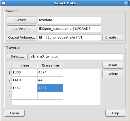
This section describes how to specify input and output data for use in Seismic Feature Enhancement. "Select Survey..." button brings up the R5000 survey selector (NOTE: The "Select Survey..." button is only visible for OpenWorks R5000). After selecting seismic survey you are able to select the seismic data Press the "Input Volume..." button and it will pop up the volume selection dialog decribed in the section below. This will allow you to select an input volume for the SFE processing. The name and the version of the volume are displayed in the text field to the right and are separated by the "|" symbol. Similarly pressing the "Output Volume..." button allows you to select the output volume for the processing. If you wish to create a new volume for the output press the "Create..." button which will bring up the Create Volume dialog.
The Traverse section of the Select Data dialog allows you to supply knee points for the SFE traverse to be created. Click the "Polygon..." button to select a Point file from the database. The coordinates of knee points will appear in the table below. Table view also allows you to edit knee points without modifying the data in the Point file.
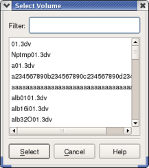
The Select Volume dialog provides you with a 3D seismic volume selector. From here simply select the seismic volume you require for your SFE processing. A volume filter is provided to reduce the list to a manageable size for projects with many volumes.
 ...
... 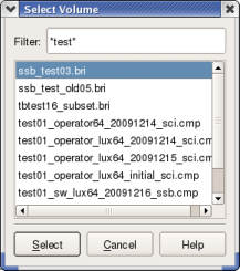
The images in the figure above show examples of the "Select Volume" dialog used for selection of a seismic volume. The LH image shows a seismic volume list without a seismic volume filter. The RH image shows the use of a filter to create a shorter list. As can be seen, the wild card character (*) can be used in the Filter field.
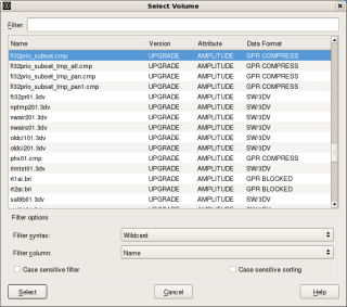
The Select Volume dialog provides you with a 3D seismic volume selector. From here simply select the seismic volume you require for your SFE processing. With OpenWorks R5000 volumes are identified by two data keys, Name and Version. Two additional attributes, Attribute and Data Format have been included for information. A Filter is provided to reduce the list to a manageable size for projects with many volumes.
 ...
... 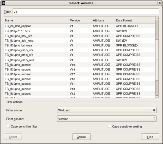
The images in the figure above show examples of the "Select Volume" dialog used for selection of a seismic volume. The LH image shows a seismic volume list without a seismic volume filter. We can filter this data in many ways. This is achieved using the Filter field in combination with the Filter column option menu item. In the RH image the list has been filtered to include only those volumes which have V1 in the Version column.
Frequently, it will be necessary to create a new seismic volume. This section describes how this is achieved. This process is easy, particularly if you accept the defaults. Click the push button to the right of the Output field to pop-up the "Create Volume" dialog.
 ...
...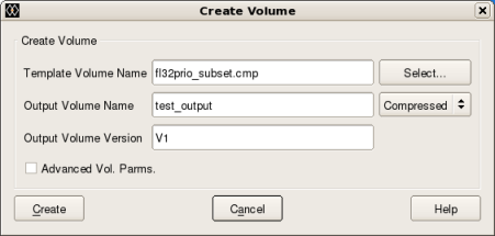
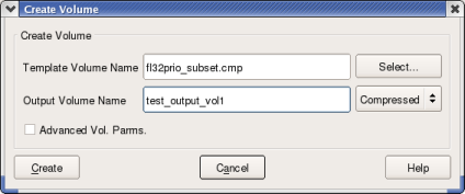
This dialog displays the various parameters required to create a new seismic volume. By default, the checkbox is turned off. In this mode, all you need to do is to select a template seismic volume, type in a name (and if OpenWorks R5000, a version) for the new volume and click the push button (see Create New Volume - basic parameters). If you need to modify the advanced volume parameters then tick the checkbox item. This will display additional parameters within three tabs: 3dv, Bricked and Compressed
Create New Volume - basic parameters
Template Volume Name: This item field allows you to select a template for the new volume via the push button. Any seismic volume can be selected, however, it is recommended that you select the input volume as this is likely to have the same areal extents.
Output Volume Name: This input field allows you to specify the name of the new seismic volume that is to be created. By default, the type of seismic volume to be created is set to be the same as the template. Again, it is recommended that you keep to the same type. If you wish to change the type of the new volume then use the combo box to the right of the "Output Volume Name" input field.
Figure 4.6. Create New Seismic Volume - Advanced Volume Parameters (.3dv Tab). 2003.12 (L), R5000 (R)
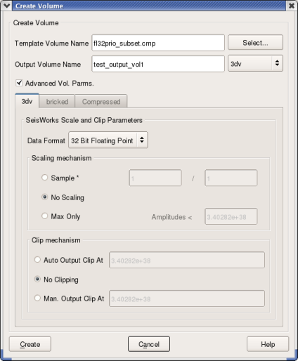 ... ...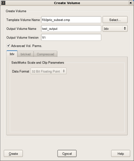 |
The image in the figure above shows the Create Volume dialog expanded to show the advanced volume parameters available for 3dv type via the 3dv tab. Note that for R5000 the Advanced Vol. Parameters have been simplified and that is now only possible to create 32bit output volumes.
Data Format: This item allows you to specify the data format of the output volume. Possible values are 32 Bit Floating Point, 32 Bit Integer and 16 Bit Integer.
Scaling mechanism: The Scaling Mechanism radio button is used to set parameters to control the conversion of seismic sample values stored in the 32 Bit Floating Point format used by Coloured Inversion to the requested SeisWorks output 3dv type. By default, the Scale and Clip Parameters frame will display scaling values as supplied in Landmark documentation. However, if the input SeisWorks 3dv class has been generated using our software, these defaults will be overwritten by scaling parameters read from our input class header file. Possible values are:
Sample * [supplied numerator] / [supplied denominator]
No Scaling
Max Only
Scaling using "Max Only" is the recommended method. Here data is scaled using the following formula:
(31 x 2(N-6))/MUA
where N is the Data Format (e.g. 16 for 16 Bit Integer) and MUA is the Maximum Unclipped Amplitude (i.e. the supplied amplitude value). An amplitude value is chosen which is representative of the maximum amplitude that is to be preserved (this is the MUA). It will be assumed that any amplitude values above this are not required. Choosing an MUA value might require you to analyse the data. This should be determined statistically, to exclude spikes and other outliers, such that normal amplitude values are less than or equal to the value set in the Amplitude field.
However, if is selected, each seismic sample value will be multiplied by the fractional scaler specified by the numerator and denominator in the text fields to the right. If is selected, the seismic sample values will be written to the output volume with no scaling.
Clipping Mechanism: This radio button item is used to control the clipping of sample values. Clipping is done after scaling and before the output data are written to disk. The possible values for the Clipping Mechanism radio button are , and Man Output Clip At. If is selected, then sample values exceeding the maximum permitted value for the requested Data Format (shown in the field to the right) are clipped to it. If is selected, then sample values will be written to the output volume without clipping. In this case, amplitudes exceeding the maximum permitted value for the requested output format will be aliased to a different lower value on output. This should be avoided as it will result in the generation of spurious data. If is selected, then sample amplitudes that exceed the value specified in the field to the right are clipped to it.
Figure 4.7. Create New Seismic Volume - Advanced Volume Parameters (Bricked Tab). 2003.12 (L), R5000 (R)
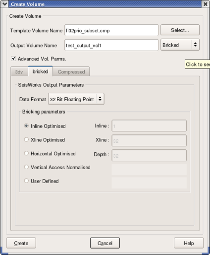 ... ...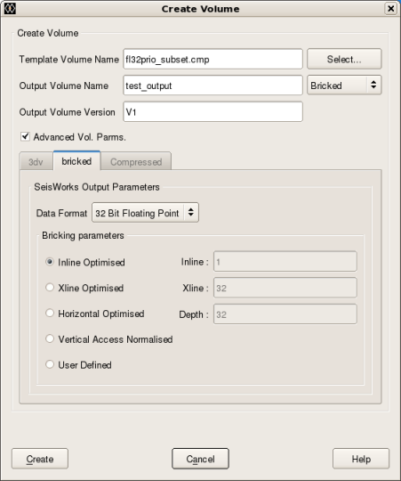 |
The image in the figure above shows the Create Volume dialog expanded to show the advanced volume parameters available for bri type via the Bricked tab.
Data Format: This item allows you to specify the data format of the output volume. Possible values are 32 Bit Floating Point, 16 Bit Float and 16 Bit Integer.
Bricking parameters: The possible values for the Bricking Parameters radio button are:
Inline Optimised
Xline Optimised
Horizontal Optimised
Vertical Access Normalised
User Defined
By default, the bricking parameter radio button is set to . If you select one of the top four options, the text fields to the right show the corresponding default brick sizes, but the fields remain desensitised. However, if you select the option, then the Inline, Xline and Depth fields to the right become sensitised, and you can specify your own brick dimensions.
Figure 4.8. Create New Seismic Volume - Advanced Volume Parameters (Compressed Tab). 2003.12 (L), R5000 (R)
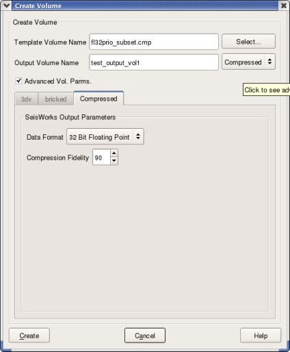 ... ...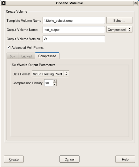 |
The image in the figure above shows the Create Volume dialog expanded to show the advanced volume parameters available for cmp type via the Compressed tab.
Data Format: This item allows you to specify the data format of the output volume. The only possible value is 32 Bit Floating Point.
Compression Fidelity: The possible values for the compression Fidelity are between 1 and 99.